How to Calculate Force (F1) for Gas Spring Sizing: An Engineering Guide to Torque and Variables
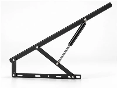
Sizing a gas spring is not simply a matter of matching the total weight of a lid to the nominal rated force of a strut. In practice, a gas spring functions as a torque-compensating element within a linkage mechanism. The force required from the strut varies non-linearly across the entire opening sweep as the lid rotates, the center of gravity shifts, and the mechanical advantage (effective moment arm) changes.
Selecting an inappropriate force rating leads directly to functional issues: an undersized gas spring cannot hold the lid open against gravity or environmental loads, while an oversized gas spring generates excessive reaction forces that can place high structural loads on hinges, distort lightweight mounting surfaces, and require higher operator effort to close.
This guide provides mechanical engineers, equipment designers, and fabricators with a structured mathematical framework to calculate required static equilibrium force, understand internal force progression, and evaluate real-world operating variables.
1. Fundamental Mechanics: Balancing Hinge Moments and Gas Spring Force
Every single-axis hinged panel operates under the principle of static moment equilibrium. To keep a lid supported in an open position or to assist an operator during lifting, the counter-clockwise moment generated by the gas spring must balance or overcome the clockwise moment generated by the lid's weight.
                  +-----------------------------------+
                  |           LID / COVER             |
                  |                o Center of Gravity (CoG)
Hinge (Pivot O)   |               /|                  |
   [O]============+==============v=+==================+
    \                           W (Lid Weight = m * g)
     \  D_s (Spring Moment Arm)
      \
       \
        \  F_spring (Gas Spring Line of Thrust)
         \
          [O] Lower Mounting Pivot
Key Geometric and Physical Variables
To analyze the mechanism, baseline parameters must be established from the CAD model or physical assembly:
- Lid Mass (m) and Weight Force (W): The total mass of the moving cover in kilograms (kg). The downward gravitational force (W) acting at the center of gravity is: W = m × g (where g ≈ 9.81 m/s², yielding force in Newtons, N).
- Center of Gravity Position (CG): The distance from the center of the hinge pivot axis to the center of mass of the lid assembly.
- Effective Moment Arm of Gravity (Dg): The perpendicular horizontal distance from the hinge pivot axis to the vertical line of action passing through the center of gravity.
- Effective Moment Arm of the Gas Spring (Ds): The perpendicular distance from the hinge pivot axis to the centerline axis (line of thrust) of the gas spring.
2. Defining Force Ratings: F1, F2, and the K-Factor
When specifying industrial gas springs, manufacturers define output force at specific points along the stroke because compressed nitrogen exhibits progressive force characteristics as the piston rod retracts into the cylinder.
Force (N)
  ^
  |
  |                     / F2 (Compressed Force Measurement Point)
  |                    /
  |                   /
  |                  /
  |                 /  Force Progression
  |                /
  |               /
  |  F1 ---------/ (Nominal Extension Force, near full extension)
  |  |           |
  +--+-----------+-------------------------> Stroke (mm)
   0 (Extended) Max Stroke
- Nominal Extension Force (F1): The baseline reference force of the gas spring in Newtons (N), specified at a standard reference temperature (commonly 20°C). It is measured under controlled dynamic extension conditions when the piston rod is near its fully extended position. Measurement points, test speeds, and testing protocols vary by manufacturer; actual force ratings and testing conditions must be confirmed against the specific manufacturer's technical data.
- F2: The manufacturer's specified force value at the defined compressed-position measurement point. The exact measurement point and testing convention may vary by manufacturer.
- The Progression Factor (K-Factor): The ratio between the compressed force and the extended force: K = F2 / F1.
Understanding Force Progression
Because a standard compression gas spring is a sealed chamber charged with pressurized nitrogen, pushing the piston rod inward reduces the net internal volume available for the gas (displaced by the rod volume). In accordance with Boyle's Law (P1 × V1 ≈ P2 × V2), this volume reduction increases the internal gas pressure.
The progression factor varies by gas spring design and should be obtained from the manufacturer's technical data or verified through testing. Key factors influencing progression include:
- The ratio of the piston rod diameter to the internal cylinder tube diameter.
- The total internal gas volume relative to the displaced rod volume.
- Internal component packaging and hydraulic oil volume.
3. Mathematical Approach for Single-Axis Hinged Lids
To estimate the static spring force required to support a lid at a given position, apply the static torque balance equation around the hinge axis:
Σ Mhinge = 0
TorqueLid = TorqueSpring
W × Dg = (n × Fspring) × Ds
Where:
- W = Total weight of the lid (N)
- Dg = Perpendicular distance from hinge axis to the vertical gravity vector (m)
- Ds = Perpendicular distance from hinge axis to the gas spring centerline (m)
- n = Number of gas springs in the system
- Fspring = Output force required from each individual gas spring at that specific angular position (N)
Note on Kinematic Directionality: This equation applies to a single-axis hinged mechanism when the gas spring line of action and its perpendicular moment arm (Ds) are correctly identified, and the spring produces an opposing moment to gravity. For other linkage geometries, multi-bar hinges, or over-center mechanisms, the actual moment direction and vector signs must be evaluated across the movement profile.
Rearranging the formula to solve for the required instantaneous gas spring force:
Fspring = (W × Dg) / (n × Ds)
Engineering Assumptions for Dual-Strut Systems (n = 2)
When using two gas springs in the equation above, the calculation assumes:
- Symmetrical mounting geometry on both sides of the enclosure.
- Approximately equal load sharing between both struts.
- Equivalent moment arms (Ds) on left and right mounting brackets.
- Consistent force characteristics between both gas springs.
In real-world equipment, structural tolerances, bracket deflection, or uneven lid stiffness can cause unequal load sharing, which should be verified during physical prototyping or structural review.
4. Illustrative Calculation: Preliminary Static Equilibrium Estimate
Disclaimer: The following values represent an illustrative engineering calculation to demonstrate the mathematical relationship. They do not constitute a final gas spring specification for a specific production build.
Assumed Example Parameters:
- Lid Mass (m): 30 kg
- Gravitational Force (W): 30 kg × 9.81 m/s² = 294.3 N
- Configuration: Dual symmetrical struts (n = 2)
- Evaluation Position: 80° open angle from horizontal
- Perpendicular Gravity Distance at 80° (Dg): 0.12 m
- Perpendicular Strut Moment Arm at 80° (Ds): 0.07 m
Equilibrium Calculation at the 80° Position:
TorqueLid = 294.3 N × 0.12 m = 35.316 N·m
Required Combined Strut Torque = 35.316 N·m
Fspring = 35.316 N·m / (2 × 0.07 m) = 252.25 N per strut
Interpreting the Single-Point Result
The calculated value of 252.25 N per strut represents only the instantaneous force needed for static equilibrium at that specific 80° position.
This single calculation does not automatically determine the nominal F1 rating to select. To complete the sizing process, engineers must evaluate:
- Stroke Position: Where the gas spring is along its stroke at 80°. If the strut is not near full extension, its available output force will reflect internal progression rather than nominal F1.
- Closed-Position Torque: The force required when the lid is closed (0°) to ensure the lid remains securely shut without excessive upward pressure on the latch.
- Mid-Stroke Transition: The hand effort required by an operator to initiate movement and control the opening rate throughout the entire sweep.
5. Key Operating Variables and Environmental Influences
A theoretical static calculation assumes an idealized, friction-free system at standard room temperature. In physical equipment, several variables alter the required force envelope.
1. Ambient Temperature Influences
Gas springs rely on pressurized nitrogen gas. In accordance with basic thermodynamic principles for an enclosed gas at constant volume (P1 / T1 = P2 / T2), internal gas pressure changes proportionally with absolute temperature (measured in Kelvin).
- Temperature Trends: As ambient temperature decreases, internal gas pressure drops; conversely, elevated temperatures increase internal gas pressure.
- Measured Output Force vs. Theoretical Pressure: In physical equipment, measured output force changes across temperature swings may not track theoretical gas pressure changes exactly. Factors such as seal friction, rod surface characteristics, and friction hysteresis can influence net force output.
- Operating Extremes: In cold environments, lower gas pressure reduces available lift-assist force. In high-temperature environments, higher internal pressure increases output force, which elevates the force required to compress the strut.
2. External Dynamic and Environmental Loads
For outdoor equipment, vehicle bodies, and industrial enclosures, static lid weight represents only part of the applied mechanical load:
- Wind Loads: An open hatch exposed to wind gusts experiences aerodynamic lift or downforce, altering the net moment around the hinge.
- Snow and Ice Accumulation: Winter precipitation increases effective lid mass and shifts the center of gravity outward.
- Vibration in Mobile Applications: Equipment mounted on commercial vehicles or vibrating machinery experiences dynamic acceleration that requires adequate holding margin at the open rest position.
3. Operator Ergonomics and Operating Effort
Acceptable manual effort during opening and closing depends on the specific machine type, user demographics, ergonomics standards, and mounting geometry:
- Opening Motion: The lid should open smoothly without sudden acceleration that could shock the hinges, while requiring minimal initial manual assistance to lift from the closed rest position.
- Closing Effort: The downward manual force required from the operator to overcome the gas spring's compressed force (F2) and moment arm (Ds) should remain within acceptable ergonomic limits for the target application.
6. Summary: Key Parameters in Gas Spring Sizing
| Parameter | Definition / Role | Sizing Influence | Reference Context |
|---|---|---|---|
| Lid Mass / Weight (W) | Gravitational force of the moving cover | Directly determines closing torque (W × Dg) | Measured mass (m × 9.81 m/s²) |
| Moment Arm (Ds) | Perpendicular distance from hinge to strut axis | Determines mechanical advantage of the spring | Defined by pivot bracket coordinates |
| Nominal Force (F1) | Rated extension force near full extension | Primary catalog selection baseline | Measured under manufacturer-defined test conditions at reference temperature |
| Compressed Force (F2) | Force at defined compressed measurement point | Determines holding and closing resistance | Governed by internal gas volume and geometry |
| Progression (K-Factor) | Ratio of F2 / F1 | Dictates force increase during compression | Varies by design; obtain from manufacturer data or testing |
| Ambient Temperature | Operating thermal range | Influences internal nitrogen pressure | Affects available output force across thermal extremes |
| Number of Struts (n) | Number of gas springs sharing load | Divides load symmetrically under balanced mounting | Symmetrical installation assumed for multi-strut systems |
7. Frequently Asked Questions (FAQs)
What happens if the selected nominal force (F1) is higher than the calculated requirement?
If the nominal force (F1) significantly exceeds the required equilibrium torque, the lid will push forcefully against its upper mechanical stops and may bounce upon reaching full extension. Additionally, closing the lid will require higher manual effort, placing higher static reaction loads on mounting brackets, hinges, and attachment fasteners when the lid is closed.
How does manual operating effort change throughout the opening sweep?
Because both the gravitational moment arm (Dg) and the gas spring moment arm (Ds) change continuously as the lid rotates, hand-effort is non-linear. In a properly designed mounting geometry, the lid remains stable in the closed position, transitions smoothly through mid-stroke with minimal operator effort, and decelerates gently as it reaches the fully open position.
Why does a gas spring feel stiffer to operate in cold winter conditions?
The perceived operating resistance of a gas spring may change in cold conditions. Depending on its design, factors such as seal characteristics, internal damping components, and mechanical friction may contribute. Actual performance should be evaluated under the intended operating temperature range.
Conclusion and Engineering Verification
Calculating nominal force (F1) provides an essential baseline for mechanism design. However, manual single-point equations evaluate only discrete positions. A comprehensive selection requires analyzing the complete torque curve from fully closed (0°) to fully open, accounting for changing moment arms, internal force progression (K-factor), and operating temperatures.
For complex geometries, heavy industrial covers, or OEM production projects, a complete 2D/3D kinematic calculation is recommended to verify hand-effort profiles and bracket reaction loads.
Suggested Internal Links
- Gas Spring Selection Guide
- Compression Gas Springs
- Engineering Support 24h Response
- Send Drawing Get Recommendation
Relevant Call-to-Action (CTA)
Submit Your Application Parameters for Kinematic Review: Send your lid dimensions, estimated weight, and target opening angle to LAND's engineering team for a full kinematic force calculation and mounting bracket recommendation.